Sorry, I am not your guy... But Zozo always puts Philips capacitors as one of the common failures on the 64KB computers. And your EP64 already has Philips capacitors.....
Another obvious question: Have you tried the OSSC on other devices to reassure it works fine?
Edit: Reading the value of an electrolytic capacitor is very easy, as it is written on the cylinder.
If you have experience in soldering it will be very easy for you to do it.
Buy one of this:

I have tried some of them, and usually the cheaper is the best... It works as a gun, you must arm the tool and then press the trigger when you have heated the tin on the hole with the point of your iron. Put the mouth of the de-solder pump near the hole you want to clean.
You have to be fast on the operation, you can't heat the hole for a long time(only a second or two every time), because then you can burn the cooper tracks.
Probably it will be better to train you on the PCB of a device you have thrown on the trash bin....
Also, electrolytic capacitors have polarity. Usually a "+" is marked on the PCB, but the capacitor makers put only a lot of "-" on the negative pin.... Just the contrary pin. Better you must guide you by the pictures of your PCB, and change them one by one. If you test the video between every individual change, still better.
Some of the capacitors you will find on the EP have a pin on every side(axial, observe how the arrow marks the right leg on the picture as the negative),
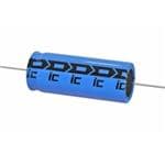
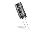
not so common today, but can be replaced with the usual component with the two legs at the same side of the cylinder(radial). The pins are usually very long, so they can fit on the same holes than the axial type, but you must isolate one of them. If it doesn't reach the holes, solder a lead on one of the legs.
The values you will read on the capacitors will be a number followed by nF, uF or pF, nano Farad, micro Farad and pico Farad. You also will read a voltage, but it is only the maximum operation voltage, so 15v or 20v is good for the EP.